|
|
|
 |
|
|
|
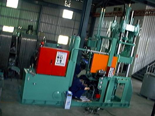
Description of Erected Die Casting System
|
|
+
Mold Locking System
-
 Casing walls are made of FCD cast iron providing sufficient rigidity and durability. Casing walls are made of FCD cast iron providing sufficient rigidity and durability.
- The locking system is comprised of integrated four units of axial subsystems, operating on vertical slide of the walls in tangent folding operation.
- The locking system is provided with HP and LP closing device to apply HP closing only after having secured the close of the metal molds to avoid damage to the metal molds.
- Casing wall is moved by adjusting four sets of locking nuts for the proper distance to the casing wall depending on the size and thickness of the metal molds.
- All fixation plate, mold adjustment plate and mold locking system are precision processed to achieve the optimal parallel among casing walls and the closeness between arms.
- Upon replacing the metal molds, adjust the mold locking system to advance or to retreat for facilitating the replacement.
- When the press plate over the mobile plate is used to press the work piece, the metal molds must be mounted first and insert the sufficient number of press bars since there are 16 cavities on the mobile plate.
- The number of press bars to be inserted varies depending on the shape of the metal molds and the plunging requirements. Make sure of the correct length of the press bars and have them arranged in flush. Have both ends of the press bar hardened by quenching.
|
|
+
Injection System 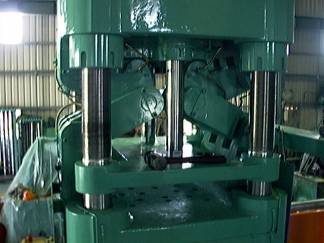 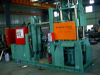
- The injection oil cylinder is directly locked to the fixation plate at accurate location, and further adjustment is not required. The enlarged space to the fixation plate facilitates the clean and maintenance routines to the peripheral of the cylinder.
- Connected to the axis of the injection oil cylinder, the injection piston is designed adjustable depending on the elevation of the initial injection position of the supply pipe built in the metal molds, to a proper position and to facilitate its replacement.
- Enlarged oil pipe for the pressure accumulator to directly prevail its function in increasing the injection speed, upgrading casting performance and consistent quality of the castings.
- Injection piston (trunk piston head) may be designed with a cooling type to provide better cooling results to the injection environment, and ensure of longer service life of the piston.
- No-load reciprocation of the injection oil cylinder could easily cause mechanical damage; if no-load reciprocation is required, do it at slower speed.
|
|
+
Press System
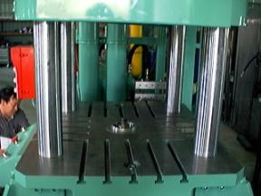
- A press fixation plate is provided on the mobile plate. By lifting the mobile plate (to open mold), the extrusion bar is plunged out. Whereas the extrusion pattern is fixed, the length of the extrusion bar determines the plunging amount of the casting product built in the molds.
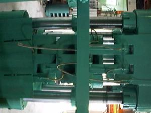
- One press oil cylinder is each provided on both sides of the fixation plate to execute the plunging movement from below. Lock both side holes disposed on both sides of the plunge plate built in the metal molds (special design) to the connection sleeve on the axis of the press oil cylinder so that upon completing the injection and the molds are opened, the push force from the press oil cylinder to plunge out the casting.
- In the use of the press from below, the plunging amount can be adjusted by the special design of the plunge plate built in the metal molds, or by direct adjustment by regulating the press travel of the press oil cylinder in addition to being adjusted by the connection sleeve on the axis of the press oil cylinder.
|
Fig. 1: Schematic view showing that the press over the Metal Molds is selected.
|
|
|
Fig. 2: Schematic view showing that the press from below is selected.
|
|
|
|
+
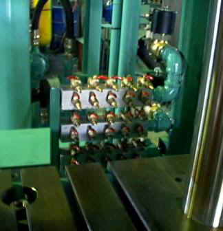
Automated Lubrication System
-
  The automated lubrication system delivers evenly distributed lubrication to all sliding or turning parts of the each mechanism, manual refill of grease is not required and mechanical tear and wear is avoided due to act of omission in manual refill. The automated lubrication system delivers evenly distributed lubrication to all sliding or turning parts of the each mechanism, manual refill of grease is not required and mechanical tear and wear is avoided due to act of omission in manual refill.
- Adjust the lubrication as applicable and the press gauge tells the lubrication status. The pressure switch also controls the lubrication.
|
|
+
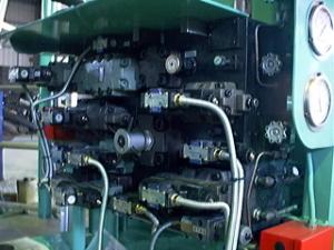
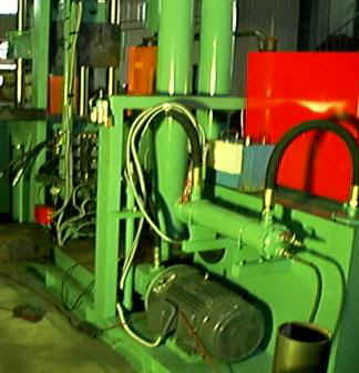
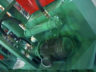
Oil Hydraulic System
- The oil hydraulic circuit includes that for opening and closing molds, injection, and press, provided in logic form to allow operation at high speed, and easier maintenance.
- Operation speed is adjustable with good consistence.
- HP seamless steel pipe is used to withstand vibration, high pressure and oil leakage.
+
Oil Spray and Air Blow Devices
- Whereas the melting alloy for casting (e.g. Zinc, Aluminum, or Copper) is inject onto the surface of the metal molds under high pressure, high speed and high temperature to create friction and welding between metals, i.e. the “sticky mold”. Therefore, before the injection of the casting alloy, a heat withstanding and inertia release agent is sprayed on the surface of the metal molds to produce a layer of hard film for preventing direct contact between the alloy and the metal molds, and improving the appearance and tensile strength of the finished product. Please carefully choose the right type of the release agent.
- Use 1/2 HP, 1/2" PT inlet air compressor to spray the release agent with the air pressure maintained within the range of 4~7 kg.
- The installation level of the release agent must not be less than 250 cm, and the pressure shall be 0~2 kg.
+
Cooling System
-
  Wider changes exist depending on the ambient temperature and the production. One
3/4" PT is provided to each water inlet of the cooling system for the injection piston, and a
1" PT is provided on the cooling water inlet at the molds to cool the entire unit. Each is provided with a water volume regulation switch. Wider changes exist depending on the ambient temperature and the production. One
3/4" PT is provided to each water inlet of the cooling system for the injection piston, and a
1" PT is provided on the cooling water inlet at the molds to cool the entire unit. Each is provided with a water volume regulation switch.
- Upon igniting the oven, turn on the cooling water at the oil cylinder piston; and upon closing the operation (to stop the machine), always wait for at least half an hour to turn off the cooling water, or the oil seal to the oil cylinder will be burnt out.
- Cooling water for the mechanical parts is pooled at the same sink to be drained through a
1"PT.
|
|
+
Combustion System
-
  Diesel or coal oil, is first pressurized by the combustor pump up to 7~9 kg/cm, and then sprayed and atomized out of the nozzle of the combustor to mix with the air delivered from within the gate, and finally ignited by a ignition stick. Diesel or coal oil, is first pressurized by the combustor pump up to 7~9 kg/cm, and then sprayed and atomized out of the nozzle of the combustor to mix with the air delivered from within the gate, and finally ignited by a ignition stick.
- If diesel or coal oil barrel is used for the combustion, the barrel must be provided at a level higher than that of the installation of the combustor, at least 70cm above the ground.
|
Fig. 3: Schematic view showing the installation of the fuel oil barrel.
|
|
|
|
|
|
|